
A dual tone horn upgrade for an EV combines high and low frequencies to create a fuller warning sound. The acoustic idea is simple; the electrical integration may not be. Electric vehicles can use different low-voltage platforms and body-controller outputs, so adding a second horn can affect load monitoring, fuse protection, voltage drop and diagnostics.
What Changes From Single to Dual Tone?
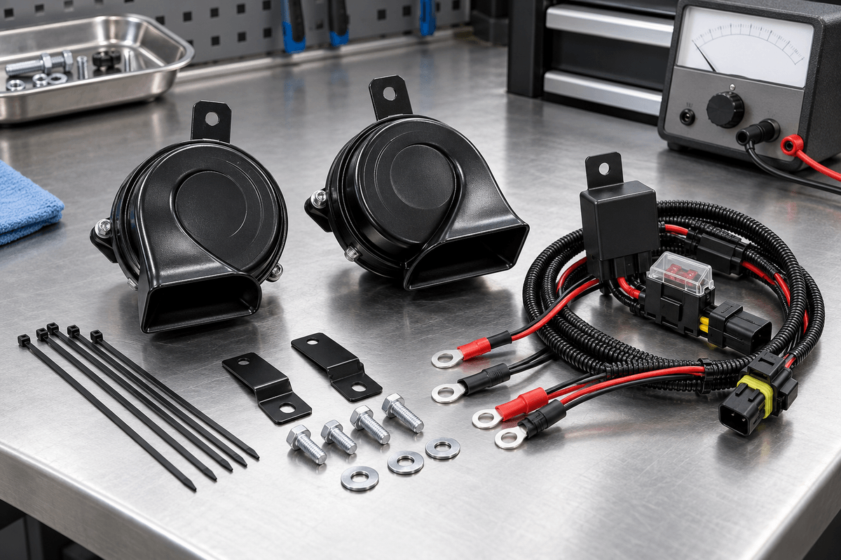
| Design area | Single horn | Dual tone pair |
|---|---|---|
| Frequency | One main tone | High and low tones must be matched |
| Current | One unit's operating load | Combined load and startup behavior |
| Mounting | One bracket and sound path | Two secure positions with similar exposure |
| Control | May use factory output directly | May require an engineered relay interface |
Confirm the EV's Low-Voltage System
Never infer voltage from the traction battery or vehicle badge. Consult the service manual for the exact model year and measure according to approved procedures. OSUN examples discussed below are marked 12V; they are not suitable for a different low-voltage platform unless an authorized design provides correct conversion and validation.
Also determine whether a body controller drives and monitors the horn. A second horn wired in parallel may exceed the output's permitted current or trigger diagnostics. A relay can move load to a fused supply, but the controller still sees the relay coil, which needs compatible current and transient suppression.
OSUN High-Low Pairing Examples
The ODL-151 disc horn imagery shows 420Hz high and 350Hz low variants, with 12V and 3A markings. Two marked 3A units suggest a simple 6A nominal sum, but procurement should confirm whether the value applies per unit and measure actual startup and steady current.
The ODL-161 snail horn is shown in 500Hz and 400Hz variants with 12V and 4A markings. Its 65mm depth and drainage design can help packaging, yet a pair still needs two clear outlets and suitable bracket space.
Pair the Acoustic and Electrical Tests
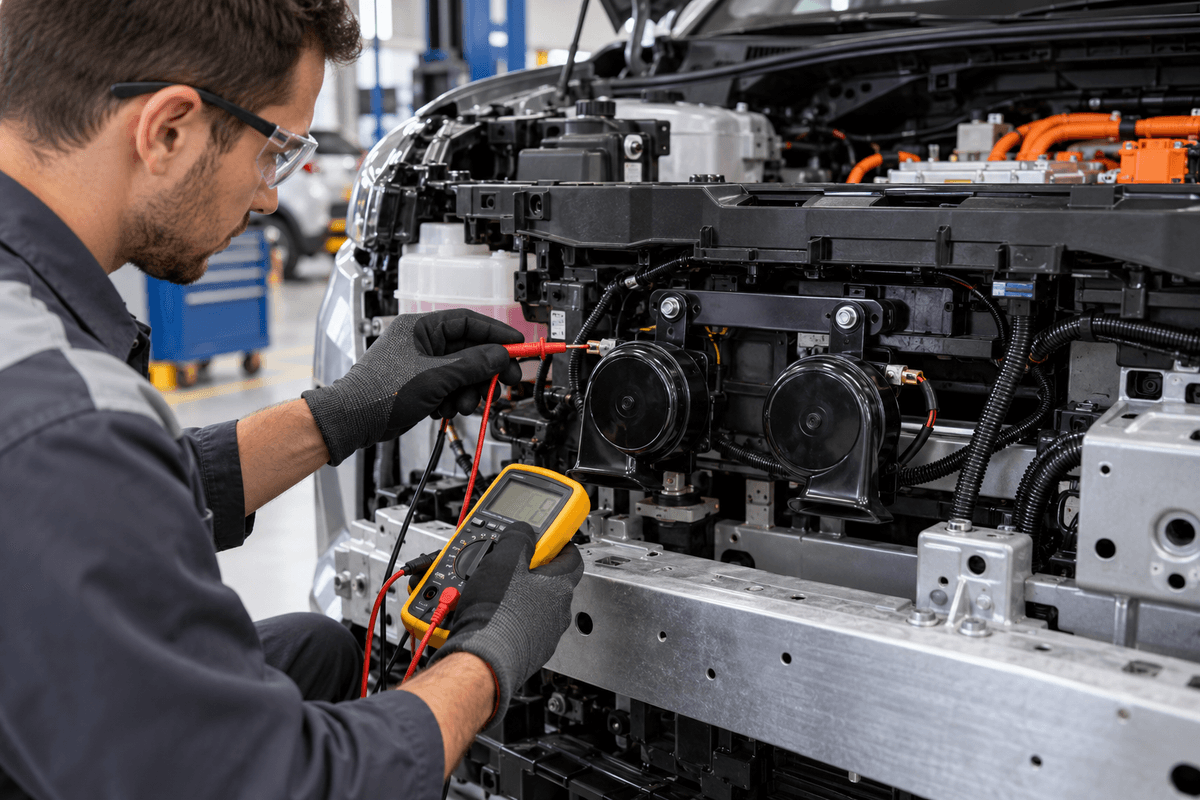
- Test high and low units separately for voltage, current, frequency and sound.
- Connect the pair using the intended harness and fuse protection.
- Measure voltage drop at each branch while both horns operate.
- Confirm neither connector or wire becomes warm after repeated cycles.
- Listen for balanced output rather than one weak or delayed tone.
- Check the completed vehicle for diagnostic faults.
- Verify installed sound against local regulations and approval needs.
Keep the Pedestrian Warning System Separate
An EV's acoustic vehicle alerting system is not a convenient trigger or power source for an aftermarket horn. It may use speakers, software and regulatory sound profiles. Modify only the driver-operated warning horn circuit in accordance with vehicle instructions, and preserve all pedestrian-warning functions.
Procurement Questions Before a Sample Order
Request high and low SKU codes, nominal frequency tolerance, current per unit, dimensions, connector drawing, mounting orientation, certificate coverage and test method. Provide the EV's low-voltage range, control architecture and available space. OSUN’s multi-fit adapter concept may help avoid wire cutting, but the exact pinout and application still need validation.
Use the OSUN contact page to request current samples and documents. Do not publish EV fitment until the complete vehicle-level test has passed.