
A single to dual horn conversion can create a fuller warning sound by combining high and low frequencies. It also doubles the number of loads, mounting points and branch connections. A splitter alone is not proof that the factory circuit can support the pair. The conversion should begin with measured current and the vehicle wiring diagram.
Calculate the New Load
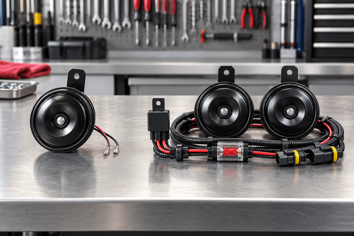
Identify the marked and measured current of each horn at the intended voltage. If two horns draw 4A each, their simple parallel total is 8A, but startup behavior and production tolerance also matter. Compare the measured pair with the factory fuse, relay contacts, wire cross-section, switch or control-module output and connector capacity.
Do not install a larger fuse to accommodate the upgrade without redesigning the circuit. A fuse protects wiring, and increasing it can leave the smallest conductor or terminal unprotected.
Direct Parallel Connection or Relay Harness?
A factory circuit may already use a relay and have adequate reserve, especially if the vehicle was offered with dual horns. Confirm from service information rather than guessing. If the original output is not designed for the combined current, a separate fused power circuit and relay may be appropriate.
The factory horn command can operate the relay coil while the relay contacts supply the pair. The design still needs:
- A relay with suitable DC contact rating and compatible coil load.
- Transient suppression appropriate for the vehicle electronics.
- A fuse close to the power source sized to protect the harness.
- Wire and terminals suitable for load, length and temperature.
- Separate secure grounds or a validated common ground point.
- Sealed connectors and strain relief in exposed locations.
Choose a Matched Frequency Pair
The OSUN ODL-151 disc horn shows 420Hz high and 350Hz low variants, with visible 12V, 3A markings. Its compact body is approximately 76mm across and 47mm deep based on the reviewed drawing. A disc pair can suit restricted depth if two mounting positions are available.
The ODL-162 snail horn imagery shows 500Hz and 400Hz variants with 12V, 4A markings. Its membrane/exhaust and anti-corrosion positioning make installation orientation and environmental validation important. Confirm the exact high and low SKUs, not just two visually similar units.
Two Horns Need Two Good Locations
Mount each horn on a rigid point with clearance for vibration. Do not stack brackets in a way that allows contact or changes adjustment. Keep outlets unobstructed and orient drainage features correctly. Avoid radiator fans, active grille shutters, heat, crash sensors and structural drilling.
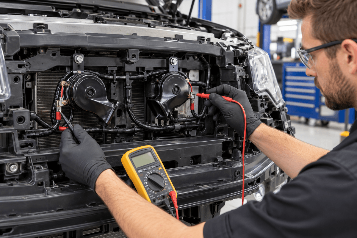
Try to give both branches similar electrical conditions. Unequal wire length, poor grounding or a weak connector can make one tone sound delayed or faint. Measure voltage drop at each horn while both operate.
Commission the Conversion
- Bench-test high and low horns separately.
- Inspect the completed harness for correct pinout and fuse location.
- Operate the pair while measuring total current.
- Measure power-side and ground-side voltage drop at each unit.
- Repeat short activations and inspect connectors for heat.
- Check diagnostic faults on electronically controlled vehicles.
- Reassemble all panels and confirm installed sound and clearance.
HELLA's workshop example reinforces the need to calculate replacement power consumption and inspect the original wiring and protection before reuse. For OSUN high-low samples, adapter options and current documents, contact OSUN. Vehicle compatibility remains subject to independent validation.