
A single to dual horn wiring harness is more than a Y-shaped cable. It must carry the combined current of two horns without excessive voltage drop, protect the smallest conductor in the circuit and connect correctly to the vehicle's horn control. A good specification starts with the vehicle circuit and the actual horn samples, not with the connector shape alone.
First Decide Which Harness Architecture Fits
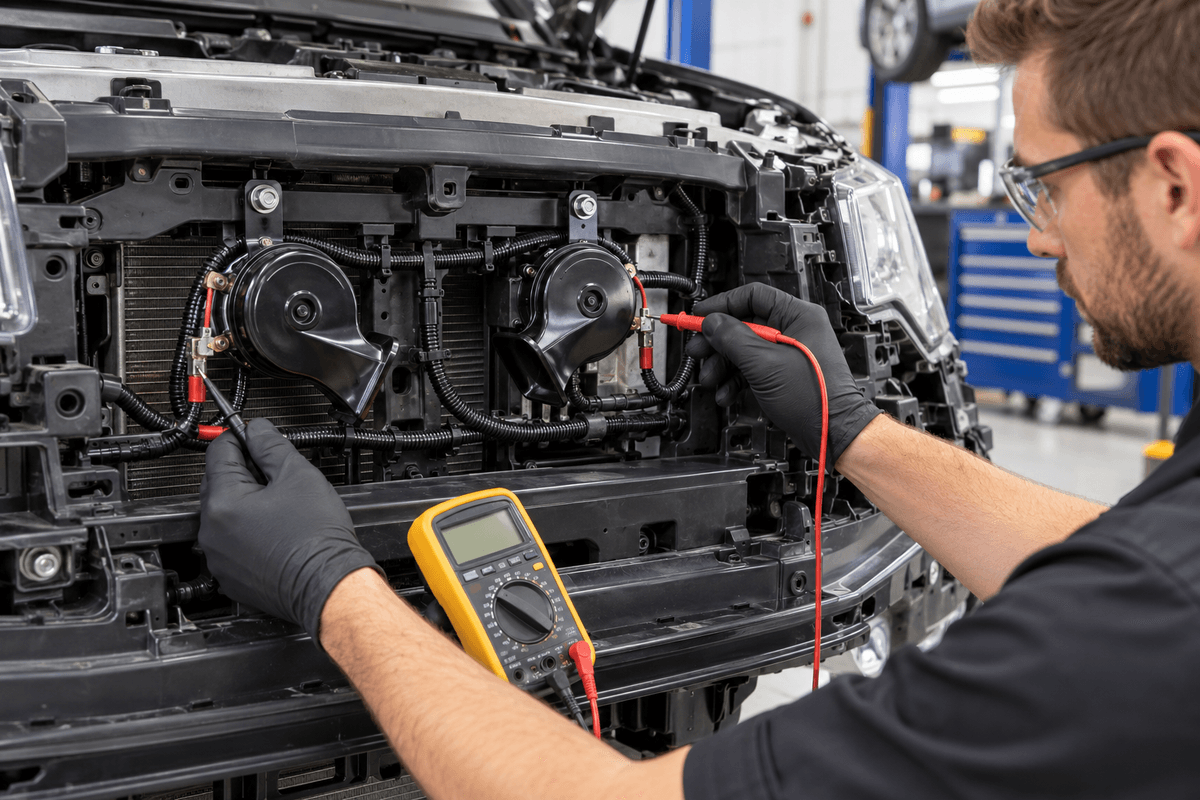
A simple splitter connects two horns in parallel to the original horn output. It can be appropriate only when the factory fuse, relay or electronic driver, wiring and connector are already rated for the pair. The fact that a plug fits does not prove that the circuit has enough electrical capacity.
A relay harness uses the original horn output as a control signal, while a separate fused feed supplies the horns through the relay contacts. It may suit a higher combined load, but a body control module can monitor current, switch the ground side or react to the relay coil. Check the circuit diagram and diagnostic behavior.
Use Real Horn Data to Size the Harness
The OSUN ODL-151 disc horn has visible 12V, 3A markings on the reviewed product imagery. High- and low-tone versions are marked 420Hz and 350Hz. A pair therefore has a 6A nominal sum based on those markings, before allowing for starting behavior, voltage variation and sample tolerance.
The OSUN ODL-161 snail horn imagery shows 12V, 4A markings with 500Hz and 400Hz options. Two marked 4A units produce an 8A nominal sum. Buyers should confirm running and inrush current on approved samples at the intended test voltage; the printed value is a design input, not a substitute for validation.
Packaging matters too. The ODL-151 drawing is approximately 76mm across and 47mm deep; the ODL-161 shows about 65mm depth, 96mm base width and 119mm height. Design branch length and connector direction around real mounting points.
Specify Every Load-Carrying Part
For a relay-based single to dual horn wiring harness, define the following items on the drawing or purchase specification:
- A fuse located close to the battery or approved power source, sized to protect the harness rather than merely prevent nuisance opening.
- A DC automotive relay with adequate contact rating, coil characteristics and protection; verify the supplier pinout.
- Wire cross-section selected for total current, branch length, allowable voltage drop, temperature and installation bundling.
- Two output branches with sealed terminals, strain relief and connector locks suitable for the chosen horn variants.
- Ground conductors and terminals rated like the positive path, with defined chassis attachment points if local grounding is used.
- Conduit, clips and grommets that prevent contact with sharp edges, heat, fans and shutters.
- Relay-coil suppression compatible with vehicle electronics and polarity.
Never solve an overloaded circuit by installing a larger fuse while retaining the original wire. The fuse must protect the smallest conductor and terminal downstream. For workshop or retail kits, print the fuse value, relay pinout and connector identification on durable labels so installers do not have to infer the circuit.
Connector Fit Is Only Half of Plug-and-Play
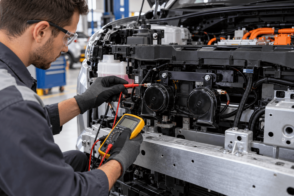
The OSUN multi-fit horn concept presents 20 connector options and highlights pure-copper terminals, low resistance and stable connection. The page uses different percentage statements for coverage, so request the application list and validate connector, polarity, latch and terminal retention for each target vehicle.
A no-cut connector can preserve the factory loom, but plug-and-play also requires suitable load, control logic, fit and sealing. Record model, year, trim, market and original connector code.
Control Voltage Drop and Branch Imbalance
Resistance at a crimp, ground stud or undersized wire can make one horn weak or delayed. Keep branch construction consistent and measure power-side and ground-side voltage drop while both horns sound; an unloaded continuity test cannot reveal this problem.
Control crimp height, pull force, terminal retention and seal compression in production. Add suitable water-ingress and corrosion checks, and keep snail-horn drainage openings correctly oriented.
A Buyer-Ready Validation Checklist
- Confirm the vehicle horn circuit, switching side, fuse, diagnostics and available current capacity.
- Measure each approved horn sample and the pair at minimum, nominal and maximum operating voltage.
- Verify wire size, fuse coordination, relay contact rating, coil behavior and suppression method.
- Check connector keying, polarity, seal, terminal retention and mating cycles.
- Install on representative vehicles; check routing, reach, clearance and drainage orientation.
- Measure voltage drop during operation, then inspect relay, fuse holder, crimps and grounds for heating.
- Run suitable environmental, vibration and endurance tests.
- Scan for faults and verify steering-wheel and security-system horn functions.
HELLA's horn replacement guidance similarly calls for calculating replacement power consumption and checking the existing wiring and protection. To develop a matched high-low horn and connector package, send the target vehicle list, available space, voltage and circuit requirements through the OSUN contact page. Final vehicle compatibility should be confirmed by the buyer's own engineering and road-legal review.