
Car horn connector types range from exposed blade terminals to sealed vehicle-specific plugs. The connector affects installation speed, weather protection, serviceability and electrical resistance. Buyers should classify more than the outside shape: terminal layout, grounding method, latch design, keying, sealing and current capacity all belong in the specification.
Common Connector Arrangements
| Connector arrangement | Typical use | Buyer check |
|---|---|---|
| Single blade terminal | Power input with bracket or case ground | Ground path, terminal width and insulating cover |
| Two exposed blades | Separate power and ground wires | Polarity, spacing, retention and weather protection |
| Two-pin sealed plug | OEM-style external installation | Keying, latch, seal, pinout and mating connector |
| Vehicle-specific molded socket | Direct replacement on named platforms | Generation, market, production date and application list |
Five Fields That Belong in Every Connector Drawing
- Front and rear housing dimensions with key and latch location.
- Cavity numbering and electrical pin assignment.
- Terminal material, plating and compatible wire range.
- Seal type, environmental rating or validation method where required.
- Mating connector or adapter code and verified vehicle applications.
Add the horn’s rated voltage and measured current because terminal suitability depends on load. Also define polarity if the product contains suppression components or electronics that make connection direction important.
OSUN’s Multi-Adapter Approach
The OSUN multi-fit car horn page shows multiple adapter styles around a shared horn platform. It describes 20 connector options, copper terminals, low resistance, stable mating and less need to cut the vehicle harness. This approach can help distributors consolidate horn-body inventory while retaining vehicle-specific interfaces.
However, connector variety is only useful when each application is controlled. The page contains both 95% and 99% coverage language, so procurement should request the current connector list and validation records rather than repeat one coverage percentage. A database should identify which adapter fits which vehicle generation and market.
Electrical and Mechanical Validation
First check terminal retention by gently pulling the wire and confirming the terminal remains locked. Mate and unmate samples repeatedly to look for bent terminals or damaged latches. Inspect seals for correct compression and strain relief for cable movement.
Then operate the exact horn and measure voltage drop across the mated connector. A continuity test with no load can miss resistance that weakens sound or creates heat. Repeat after vibration, water or temperature conditioning when the target environment requires it.
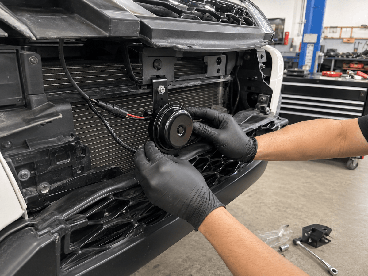
Physical fit extends beyond the plug. The harness should not be stretched, sharply bent or routed near the radiator fan, exhaust heat or edges. The connector must remain accessible enough for service while protected from direct spray. HELLA’s replacement guidance likewise emphasizes model-specific mounting, secure cable routing and verification of the existing circuit.
Packaging and Warehouse Controls
- Give every adapter a unique code and clear product photo.
- Separate visually similar connectors in divided packaging.
- Include the approved vehicle list and horn model on the label.
- Use terminal caps or trays to prevent bending during shipment.
- Check adapter identity during kit packing and final inspection.
Buyers can request connector drawings, pinouts, samples and application data through OSUN’s contact page. Match those documents to the chosen product in the OSUN horn range before releasing packaging claims.