
The difference between a high tone and low tone car horn is primarily frequency. A high-tone unit vibrates at a higher frequency and often sounds brighter or sharper; a low-tone unit sounds deeper. Many vehicles combine the two to create a fuller, more recognizable warning. The right choice still depends on vehicle design, legal requirements, electrical capacity and available mounting space.
Frequency Is Not the Same as Loudness
Frequency is measured in hertz and describes how rapidly the sound waveform repeats. Sound pressure is measured in decibels under specified conditions. A 500 Hz horn is not automatically louder than a 400 Hz horn, and a low tone is not automatically more powerful. Housing, diaphragm, resonator, voltage, current, mounting and test distance all influence the result.
Perception also changes inside and outside a vehicle. A dual-frequency sound can be easier to distinguish amid road noise, while a single compact unit may be appropriate where space and circuit capacity are limited. Buyers should listen to controlled samples rather than choose from “high” or “low” wording alone.
OSUN Frequency Examples Make the Choice Concrete

The OSUN ODL-151 disc horn product image shows high and low variants marked at 420 Hz and 350 Hz, together with 12V, 3A and 110 dB markings. Its reviewed drawing indicates an approximately 76 mm body width, 47 mm depth and an 8.5 mm mounting hole, making physical fitment an important part of tone selection.
The ODL-161 snail horn images show 500 Hz and 400 Hz high/low variants with 12V and 4A markings. The page also highlights a 65 mm slim design, forward sound direction and water drainage. Buyers should confirm all values against current samples and ask whether the stated current applies to each unit.
Single Tone or High-Low Pair?
A single horn reduces component count, wiring load and space requirements. It can suit direct replacement programs where the vehicle originally uses one device. A high-low pair creates two frequency components and often produces a richer warning character, but it also needs two mounting positions, appropriate connectors, a capable relay or control circuit, suitable wiring and fuse protection.
Do not connect a second horn merely because the bracket has space. Compare total measured current with the factory circuit. Check voltage drop at both horns and make sure one branch does not receive a better ground or supply than the other. Unequal electrical conditions can make a pair sound unbalanced.
Buyer Listening and Measurement Checklist
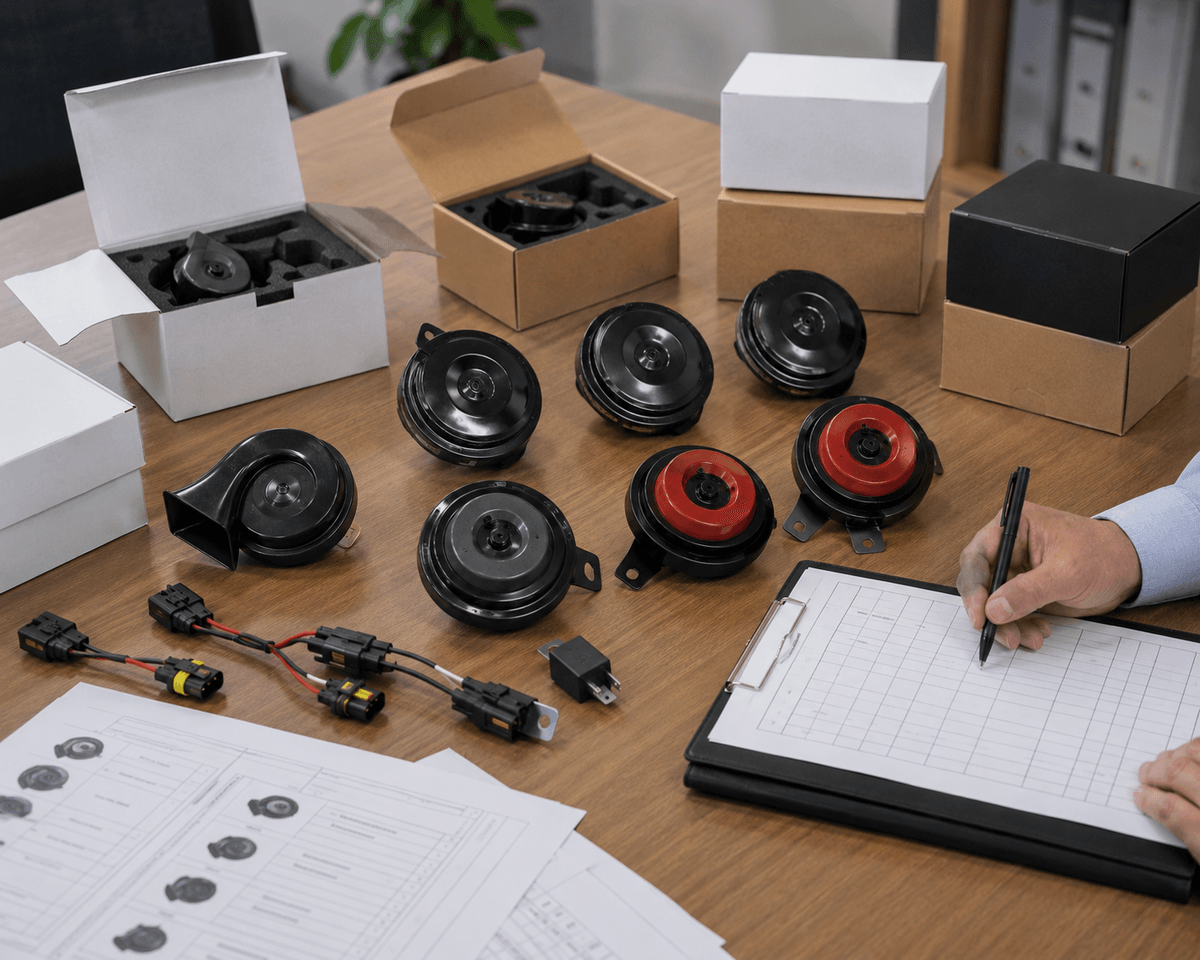
- Confirm each unit’s nominal frequency and allowable tolerance.
- Record test voltage, distance, microphone position and acoustic environment.
- Compare each horn separately before evaluating the pair.
- Measure current and voltage at the horn while it operates.
- Check tone stability across multiple samples and repeated activations.
- Verify bracket stiffness, outlet direction, drainage and nearby obstruction.
- Match approval documents and markings to high, low and paired SKUs.
Plan the Product Line Around Applications
For distributors, the useful range is not simply “high” and “low.” Define compact disc replacements, slim snail options, E-mark requirements, connector coverage, single-unit kits and paired kits. Packaging should identify voltage, tone, frequency, connector, dimensions and whether one or two units are included. This reduces installation errors and returns.
OSUN’s horn range includes disc, snail, sports and multi-fit concepts that can support different positions in an aftermarket catalog. Ask OSUN to confirm the exact SKU marking, frequency tolerance, current, sample test method, bracket drawing and certificate through the contact page.