
There is no single amperage for every car horn. Current draw changes with horn construction, rated voltage, single or dual configuration, supply voltage, internal adjustment, temperature and product condition. The useful answer is the current of the exact horn or pair under a defined test—not a generic value copied into a fuse calculation.
Useful OSUN Reference Points
| OSUN example | Visible marking | Buyer verification |
|---|---|---|
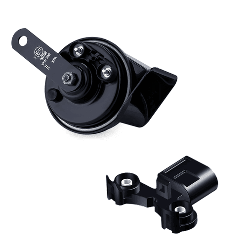
| ODL-151 disc horn | 12V, 3A; 420/350 Hz variants shown | Confirm whether order is one tone or a pair and match sample marking |
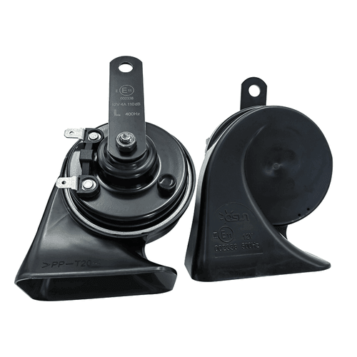
| ODL-161 snail horn | 12V, 4A; 500/400 Hz variants shown | Verify current per unit, connector, wire and high/low combination |
| ODL-162 snail horn | 12V, 4A; 500/400 Hz variants shown | Confirm exact SKU, approval marking and measured lot result |
These values come from reviewed product images and should be confirmed against the current sample and specification. If two 4A horns are connected in parallel, the simple marked-load total would be 8A. Real operating behavior can differ, especially during initial actuation or when system voltage and wiring resistance change.
Power Can Provide a First Estimate
When a supplier gives watts rather than amps, the basic relationship is current equals power divided by voltage: I = P / V. A 60W load at a nominal 12V gives a simple estimate of 5A. However, a running vehicle may operate above 12V, horn current is not perfectly constant, and catalog power may be rounded or specified under a particular condition.
HELLA’s published retrofit example lists 66 watts for two horns and explains this as approximately 11A in a 12V vehicle system. That documented pair is a useful reminder that product-specific data matters; it should not be used as the expected current for an OSUN model or another horn.
Measure Current Without Creating a Short
A DC current clamp around one supply conductor is often the least disruptive way to observe horn current. Zero the clamp, select an appropriate range, operate the horn briefly, and capture both the initial and steady reading if the instrument allows. Compare the result with the product specification and repeat at a controlled battery voltage.
An inline multimeter current test is only appropriate when the meter, leads, internal fuse and input terminal are rated for the expected current. Connecting a meter in current mode directly across the battery or horn supply creates a short circuit. Follow the meter manual and vehicle service information, or use a qualified automotive electrician.
Why Current Data Matters to Buyers
- Wire cross-section and connector temperature depend on actual load and route length.
- The fuse must protect the circuit while tolerating normal operating behavior.
- Relay contacts need adequate DC load capacity and service life.
- A dual-tone pair can require substantially more current than a single horn.
- Excess current may indicate an internal fault, wrong voltage or mechanical problem.
- Low current with weak sound can indicate voltage drop or poor connections.
Put a Current Test in the Purchase Specification
Ask the supplier to state rated voltage, marked current, test voltage, number of horns, ambient condition, activation time, and allowable range. Define whether inspection records the peak, steady-state value, or both. Keep the same fixture, power source and measurement method for golden-sample and batch comparisons.
The compact ODL-151 disc horn and the drainage-oriented ODL-161 snail horn represent different package and load choices. Buyers should send target vehicle, tone pair, connector and circuit limits through OSUN’s contact page before sampling.