
A car horn can show battery voltage at an unplugged connector and still sound weak when connected. The reason is that a high-resistance wire, terminal, relay contact or ground may pass enough current for a meter reading but not enough for the loaded horn. A voltage drop test exposes that restriction while current is flowing.
Why Continuity Alone Can Mislead
A continuity test uses very little current. A corroded connection may beep successfully yet lose significant voltage when the horn draws several amps. Fluke’s automotive guidance emphasizes testing an energized circuit: place the digital multimeter across the section being evaluated and read the electrical pressure lost through that wire, switch, connector or ground path.
Before working, secure the vehicle, keep probes away from moving parts, and consult its wiring diagram. Some horn circuits are ground-switched or controlled by electronics. Do not access airbag wiring or steering-wheel components without the manufacturer’s procedure.
Test the Positive Side
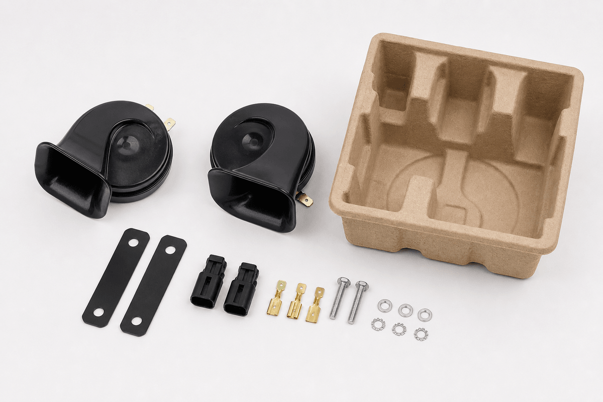
- Set the meter to DC volts with the leads in COM and V/ohm terminals.
- Place one probe on the battery positive post and the other at the horn’s positive supply terminal.
- Have a helper press the horn briefly while you observe or capture the reading.
- If the drop is excessive for the vehicle specification, divide the path and test across the fuse, relay contacts, connectors and wire sections.
The meter displays the voltage consumed by resistance between its probes. Moving step by step along the path isolates the connection or component responsible.
Test the Ground Side
Place one probe on the horn ground terminal or verified metal case ground and the other on the battery negative post. Operate the horn. A healthy ground path should have very little voltage across it; a larger reading indicates resistance. Inspect painted mounting points, corrosion, loose fasteners, small ground wires and damaged terminals.
Fluke provides general diagnostic guidance such as approximately 0.20V across a wire or cable, 0.30V across a switch, and 0.10V at a ground when manufacturer values are unavailable. These are troubleshooting references, not universal acceptance limits. Vehicle and product specifications should take priority.
Use the Result With Current and Sound
- High positive-side drop: inspect fuse contacts, relay contacts, connectors and supply wiring.
- High ground-side drop: clean or repair the ground path and mounting connection.
- Low drop but weak sound: verify battery voltage, horn condition, mounting and outlet obstruction.
- Correct supply but no operation: confirm the exact horn with a protected bench test.
- Changing results: look for heat-sensitive contacts, vibration, moisture or intermittent wiring.
Connect the Test to OSUN Product Selection
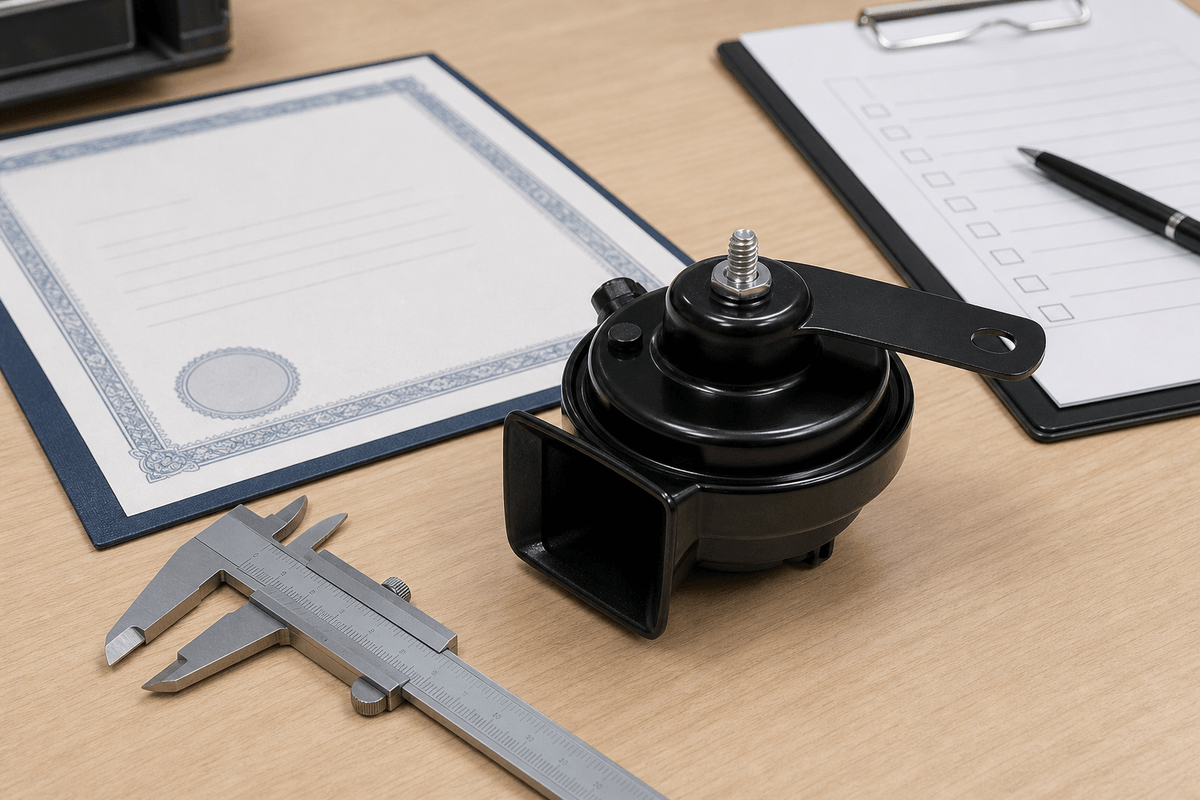
The OSUN ODL-151 image shows a 12V, 3A marking. The ODL-162 snail horn image shows 12V and 4A. Because voltage drop increases with current for a given resistance, a marginal connector may become more obvious after changing to a different horn or adding a second tone.
OSUN’s multi-fit horn page highlights pure copper terminals, low resistance and stable connection. Those are relevant design goals, but buyers should verify connector fit and perform loaded measurements on the actual adapter and vehicle. Broad connector coverage language does not guarantee a low-resistance fit on every application.
A Repeatable Incoming and Installation Check
Record battery voltage, voltage at the operating horn, positive-side drop, ground-side drop, current draw and sound result. Use the same test duration and probe points. For production qualification, define maximum values with the vehicle maker, harness designer or responsible engineer rather than inventing a threshold.
After repair, operate the horn repeatedly, inspect for terminal heating and confirm the fuse remains correct. Buyers can provide circuit drawings, target current and connector requirements through the OSUN contact page when requesting samples.