
A silent horn does not always mean the horn itself has failed. The fault may be a fuse, relay, switch circuit, connector, ground, or damaged wire. A multimeter helps separate those possibilities, but the test must follow the vehicle wiring diagram because some systems switch power, some switch ground, and many modern vehicles route the command through electronics.
Prepare the Circuit Safely
Park securely, switch off the ignition unless the service procedure requires it, keep hands clear of fans and belts, and locate the correct fuse and relay information. Do not probe steering-wheel airbag circuits or dismantle the steering wheel without the manufacturer’s safety procedure. Use fused test leads where practical and never place the meter in current mode directly across the battery or horn connector.
You will need a digital multimeter, wiring information, insulated back-probes, and ideally a helper to press the horn control. First inspect the horn, bracket, connector, harness, and fuse. Green corrosion, a loose ground, chafed insulation, or a burnt terminal may explain the failure before electrical testing begins.
Step 1: Check Supply Voltage at the Horn
Set the meter to DC volts. Connect the black lead to a known good chassis ground and the red lead to the horn’s supply terminal. Have a helper operate the horn. A reading close to battery voltage suggests that power reaches the connector; no voltage points upstream toward the fuse, relay, control, or wiring.
If the vehicle uses a ground-switched circuit or a two-wire connector, follow its diagram rather than assuming the case is ground. Measuring across the two connector terminals while the horn is commanded can show whether the circuit supplies the expected potential difference.
Step 2: Test the Ground Under Load
A continuity beep with the circuit off can miss a high-resistance connection. Voltage-drop testing under load is more revealing. With the horn commanded, measure between the horn ground point and battery negative. A significant voltage reading means energy is being lost across the ground path. Clean and secure the connection, then retest using the vehicle maker’s allowable voltage-drop value.
The same approach can be used on the power side by measuring between battery positive and the horn supply terminal while operating the horn. Excessive drop suggests resistance in wiring, relay contacts, connectors, or the fuse path.
Step 3: Check the Horn and Control Components
Disconnect power before resistance or continuity testing. A fuse can be checked for continuity after removal. Relay coil and contact checks should follow terminal identification and service specifications. Resistance across a horn alone is not always a decisive pass/fail test because electromagnetic horn construction and meter behavior vary. If correct voltage and ground are present under load but the horn remains silent, a controlled bench test or replacement with a known-good unit is more useful.
- No command voltage: inspect fuse, relay control, switch input, and wiring.
- Voltage present but large power-side drop: inspect contacts and connections.
- Good power but poor ground: repair the ground path or mounting connection.
- Good power and ground but no sound: verify the horn with a fused bench test.
- Fuse blows during testing: stop and locate the short or excess current draw.
Match the Replacement to the Circuit

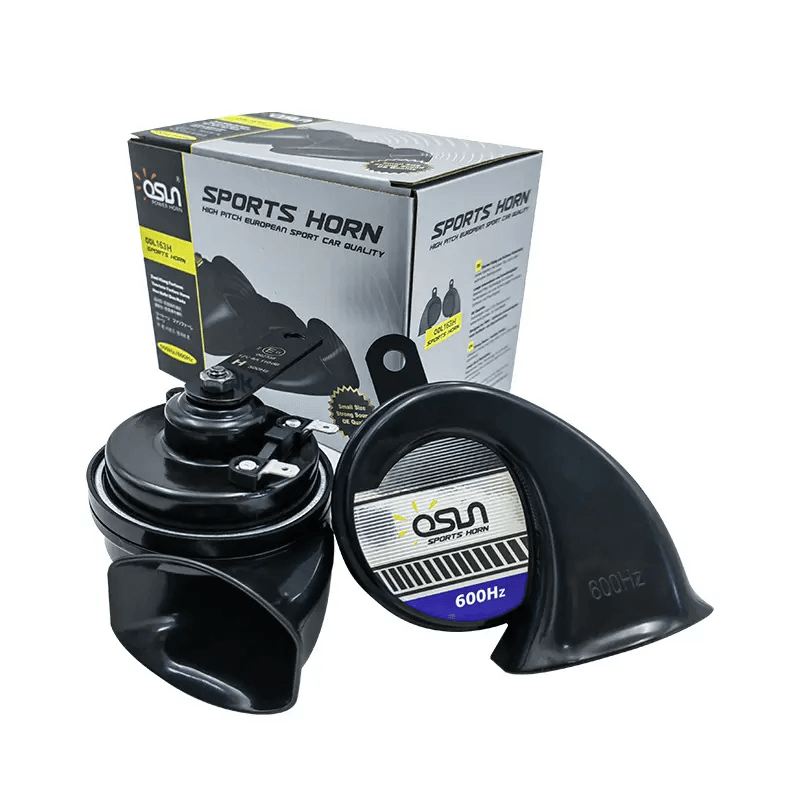
Electrical fit matters as much as sound. The OSUN ODL-151 disc horn has a visible 12V, 3A marking, while reviewed OSUN snail and sports horn images commonly show 12V and 4A. Use the exact sample specification rather than assuming all horns draw the same current. Confirm wire gauge, fuse, relay capacity, connector polarity, and mounting ground before installation.
The ODL-161 snail horn also adds physical checks: approximately 65 mm depth, an 8.5 mm mounting hole, and a drainage-oriented design. Keep the outlet and drainage path correctly oriented. For model recommendations and current documentation, contact OSUN with the vehicle circuit and application details.