
A plug and play car horn replacement should connect without cutting the vehicle harness, mount securely and operate within the original circuit’s limits. A connector that clicks into place is only one part of that promise. Pin assignment, polarity, current demand, fuse and relay capacity, bracket geometry, clearance and sound requirements must also match.
Define Plug and Play in the Product Listing
For some sellers, “plug and play” means an adapter is included. For a workshop, it may imply no wire cutting, no added relay, no drilling and no warning messages. Those are different claims. A responsible application listing should state exactly what is reused and what may require modification.
At minimum, verify:
- Vehicle make, model, generation, year and market.
- Connector housing, keying, terminal count and pin assignment.
- Power-switched or ground-switched circuit behavior.
- Horn voltage and measured current, including single or dual configuration.
- Factory fuse, relay, wiring and control-module capacity.
- Bracket hole, offset, body depth and outlet clearance.
- Required approval and permitted sound character.
How OSUN’s Multi-Fit Concept Helps
The OSUN multi-fit car horn page presents a 20-adapter concept intended to broaden vehicle coverage and reduce distributor inventory. It highlights OEM-style connection, copper terminals, low resistance and avoiding broken factory wires. This can simplify installation where the correct adapter has been validated.
The page uses both 95% and 99% coverage wording, so buyers should not repeat one percentage as a universal guarantee. Request the current adapter list and map each connector to a verified vehicle application. Connector shape alone is insufficient; check pin function and electrical behavior.
Match the Horn Body to the Vehicle
For compact locations, the ODL-151 disc horn drawing indicates approximately 76mm body width, 47mm depth and an 8.5mm mounting hole. Its visible marking shows 12V and 3A. Even with a correct plug, buyers must confirm that the bracket angle, overall height and terminal direction avoid bodywork and moving components.
A snail design has additional orientation needs. The ODL-161 page emphasizes forward sound direction and drainage in a body approximately 65mm deep. The outlet should remain clear, and installation should avoid direct water collection, hot components and cable strain.
Check the Circuit Before Calling It Direct Fit
Measure voltage at the original horn while it operates and compare the new product’s current with vehicle data. If changing from one unit to a high-low pair, combined current may exceed the original arrangement. A relay harness might be required, but it must be designed with suitable wire, fuse, terminals, coil suppression and grounding.
Modern body control modules may monitor the horn output. An electrically different load can cause faults even when it sounds. Vehicle-specific service data and a controlled sample installation are essential before publishing broad compatibility.
Application Validation Workflow
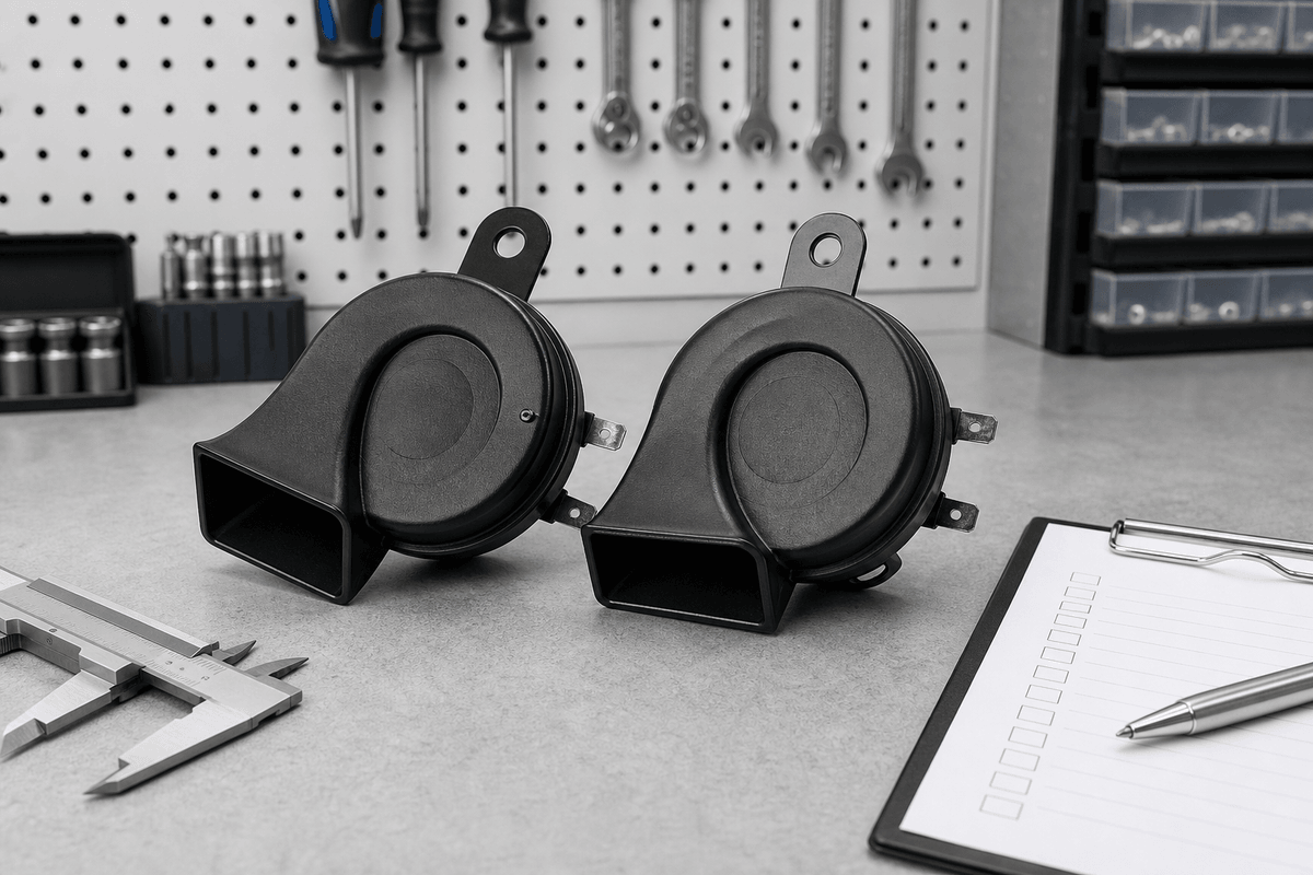
- Photograph and identify the original connector, bracket and horn marking.
- Confirm adapter keying, terminal retention, polarity and pull-out resistance.
- Measure available space and compare the complete mounted envelope.
- Test operating current, supply voltage and voltage drop.
- Check repeated function, fuse behavior, connector temperature and sound.
- Inspect clearance and water orientation after bumper or grille refitting.
- Record the validated application and any installation notes.
For distributors, this vehicle-by-vehicle evidence is more valuable than an unsupported universal-fit statement. Use OSUN’s horn range to choose a physical design, then request adapter drawings, electrical data and samples through the contact page.